Installing residential network wiring
The goal of this project was to install network wiring throughout a house that only had the cable line in from the ISP. The house is a split level
with four levels. The bottom basement is unfinished, but also has the cable
line and modem installed on an unfinished wall. The primary need for this project was
to wire up the bedroom used as an office, so wireless wouldn’t be the only option.
As an initial solution, I bridged an old Linksys router to our main wireless access point. This provided wired connections in the office without having to run wires the entire way. However, the Linksys router was slower than the bandwidth from the ISP, and was likely slowing down the wireless for all other connected devices. The router was also unreliable and required rebooting every few days. This was not the ideal situation to work on computers that might have other networking problems. Also, I felt that if I was not getting the full bandwidth from the ISP, I was cheating myself.
One solution would have been to replace hardware in the office to have a faster, more reliable bridge. I weighed the option, but decided that if I were going to spend any money, I’d prefer to fully wire the house. Then it would have a very reliable infrastructure that would not need replacing for many years.
After planning, the project included several sections, including installing a rack and network equipment in the basement. The major part was finding wiring paths that made sense, drilling holes, and running fish tape and cable. Finally, terminating keystones, the patch panel, closing up holes, and cleaning up took quite a lot of effort. In the end I had seven finished wall plates with two RJ45 jacks each. This includes one plate in the front room, two in the family room, one in the office, and one in each of the three bedrooms.
The majority of the wiring runs vertically into the attic, and back down through the walls into the various locations. We managed to line up this initial run to a section of wall where the gap was literally the width of a single stud. A little bit of it was luck, but a lot of it was the skill and experience that my friend brought.
electricians scissors
110 punchdown
cable jacket stripper
cable cutter
jab saw
crimp tool
drill
screwdrivers
pliers
stud finder
specialty drill bits
wire pulling rods
tone & probe kit
Materials included:
500ft fish tape
1000ft CAT6 STP
CAT6 Keystones
wall plates
low voltage wall brackets
cable ties
cable tie mounts
8U wall rack
mounting hardware for rack
24 port CAT6 shielded patch panel
24 port Gigabit switch
spray foam insulation
blown-in insulation
fastening tape
2 ft CAT6 patch cables
grounding wire
wire ring terminals
electrical tape
The entire purchasing process took a lot of searching, several online transactions, and several trips to different hardware stores. In all I spent about $600 on this project, although some of the tools were borrowed. I managed to get a sweet deal on the gig switch from an out of luck bitcoin mining operation.
There were also several places where the blown-in insulation was disturbed in the attic. I also realized that it was a bit low in some areas, so I added 7 bags of insulation by hand. It would have been better to rent an insulation blower, but 7 bags was not enough to rent one. It was however tedious work. This step was performed over two days.
As an initial solution, I bridged an old Linksys router to our main wireless access point. This provided wired connections in the office without having to run wires the entire way. However, the Linksys router was slower than the bandwidth from the ISP, and was likely slowing down the wireless for all other connected devices. The router was also unreliable and required rebooting every few days. This was not the ideal situation to work on computers that might have other networking problems. Also, I felt that if I was not getting the full bandwidth from the ISP, I was cheating myself.
One solution would have been to replace hardware in the office to have a faster, more reliable bridge. I weighed the option, but decided that if I were going to spend any money, I’d prefer to fully wire the house. Then it would have a very reliable infrastructure that would not need replacing for many years.
 |
| An old Linksys WGR54GS device used as a wireless bridge |
Overview
After planning, the project included several sections, including installing a rack and network equipment in the basement. The major part was finding wiring paths that made sense, drilling holes, and running fish tape and cable. Finally, terminating keystones, the patch panel, closing up holes, and cleaning up took quite a lot of effort. In the end I had seven finished wall plates with two RJ45 jacks each. This includes one plate in the front room, two in the family room, one in the office, and one in each of the three bedrooms.
Rack and wall equipment
For rack equipment I first mounted a sheet of plywood to wall studs in the basement. This provided space to mount a 12” 8U rack which holds a 24 port patch panel and 24 port switch, with room to grow. I also mounted a grounding bar, power strip, cable modem, wireless router, and cable splitter to the wall for a clean and organized wiring wall.Cable installation
Routing the cables was probably the biggest challenge for me. Luckily, I managed to get a work friend over to help me who has a career of experience in cable installation. He gave guidance on wire paths, where to place jacks, and helped me drill holes and pull fish tape. I owe him big time.The majority of the wiring runs vertically into the attic, and back down through the walls into the various locations. We managed to line up this initial run to a section of wall where the gap was literally the width of a single stud. A little bit of it was luck, but a lot of it was the skill and experience that my friend brought.
Finishing cables
The wires we pulled are CAT6 STP. I chose shielded because it wasn’t that much more expensive than unshielded. The cable isn’t riser or plenum rated, but this is a residence, not a place of business. Terminating wire at the patch panel and jacks was fairly straight forward and went without many problems. The catch with shielded cable is that it must be grounded or it can act as an antenna and receive even more interference, so I made sure to get a shielded CAT6 patch panel and ground it to the breaker box.Cleanup
Cleaning up after the project was not something that I planned initially, but sealing the holes for wire runs, and restoring insulation where it was disturbed actually took a lot of time and effort.Detailed Work
Acquire tools & materials
Tools included:electricians scissors
110 punchdown
cable jacket stripper
cable cutter
jab saw
crimp tool
drill
screwdrivers
pliers
stud finder
specialty drill bits
wire pulling rods
tone & probe kit
Materials included:
500ft fish tape
1000ft CAT6 STP
CAT6 Keystones
wall plates
low voltage wall brackets
cable ties
cable tie mounts
8U wall rack
mounting hardware for rack
24 port CAT6 shielded patch panel
24 port Gigabit switch
spray foam insulation
blown-in insulation
fastening tape
2 ft CAT6 patch cables
grounding wire
wire ring terminals
electrical tape
The entire purchasing process took a lot of searching, several online transactions, and several trips to different hardware stores. In all I spent about $600 on this project, although some of the tools were borrowed. I managed to get a sweet deal on the gig switch from an out of luck bitcoin mining operation.
 |
| Some of the tools used for this project |
Cut and mount plywood to wall studs
I already had the plywood, but had to cut it to the right shape with a jigsaw, measure and drill pilot holes for wood screws to securely mount it onto the wall. I used nine 2 ½” screws, thinking that the plywood will possibly hold a lot of weight.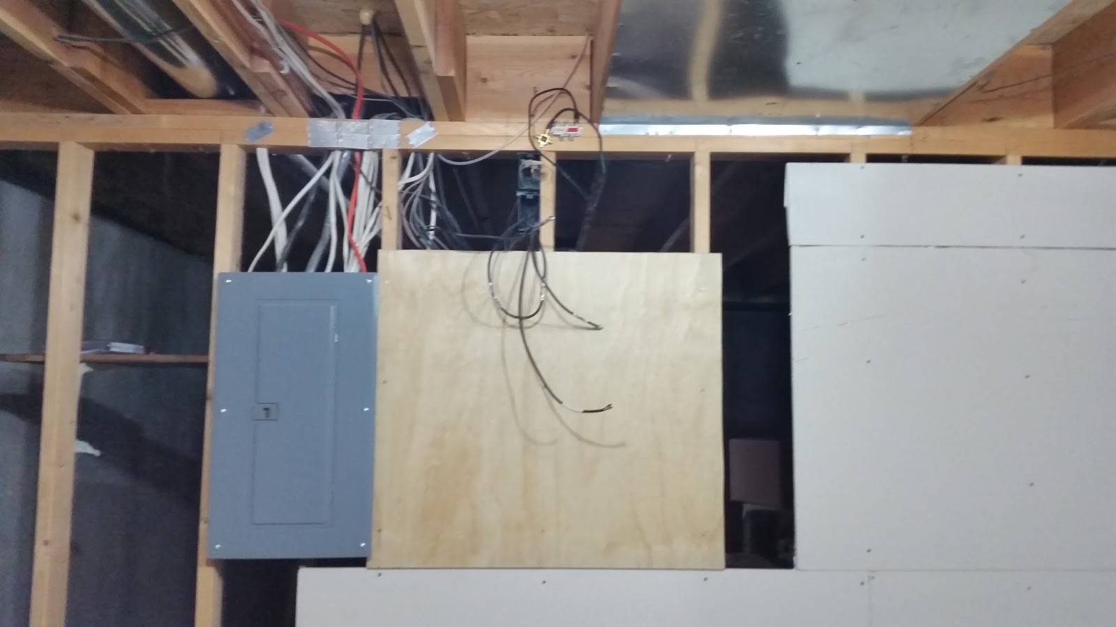 |
| Plywood mounted to wall studs near cable up-link |
Route fish tape, measure, drill, and pull cable
The easiest route for the majority of the wiring was not the
shortest, and it wasn’t that easy. We drilled vertically from the
basement into the main level wall, then from the attic into the same
section. This section needed to hold 12 cables, so several holes were
drilled in sequence. After reaching the attic, the majority of the cable
ran over to the upper attic above the bedrooms. Three holes were
drilled from the upper attic into different wall sections; two for
bedrooms. One line had to go all the way from the upper attic through
the upstairs wall, and into the upper basement wall. This was the most
difficult section to drill, and we had to make a couple of extra holes
in the wall to drill the correct holes in studs. That location was also
where I needed the network the most.
Fish tape was pulled using rods. At this point, holes were also cut for the plates in various rooms. After fish tape was in place, cable was measured, cut, and pulled through to the appropriate location. In all there are 16 lines run to 8 locations. 7 of these locations are in finished rooms.
This step was completed over 4 days.
 |
| A hole in the attic into a section of wall |
 |
| This stud finder shows the small gap between studs that we managed to route most of the cables |
 |
| Fish tape pulled to a wall jack |
 |
| Low voltage wall bracket installed |
 |
| Cable bundled, tied to fish tape, and then secured with electrical tape for pulling |
Install wall rack and hardware
The 12” 8U rack had to be assembled and installed on the plywood. Tee
nuts were used to provide a secure mount to the plywood. Additional
screws were installed for mounting the cable modem, wireless router, and
power strip. I also mounted the cable splitter as well as a grounding
bar.
The patch panel and network switch mounted to the rack, leaving 6U for future expansion. Both the rack itself and the patch panel were grounded to the bus bar, and the bus bar grounded to the electrical panel.
The patch panel and network switch mounted to the rack, leaving 6U for future expansion. Both the rack itself and the patch panel were grounded to the bus bar, and the bus bar grounded to the electrical panel.
 |
| 8U 12" wall mount rack installed on plywood |
Terminate cable at patch panel and wall jacks
Cables needed to be cut to length, stripped, and punched down on the patch panel, as well as on keystone jacks at each wall mount. Plate holes needed to be finished and brackets installed. Keystones mounted into the wall plates. Each cable had foil shielding as well as an additional stranded copper wire for grounding. This attached at the patch panel. Patch cords connected the panel to the switch, switch to the router, and router to the modem. Cables were tidied up with Velcro and cable ties. |
| The first two cables punched down into the CAT6 shielded patch panel. Ground not yet connected |
 |
| Keystone jacks punched down, and installed into a wall plate |
 |
| A finished wall plate with two jacks |
Cleanup
There were several holes in studs from the attic or basement that needed repair. Foam insulation from a can was used to seal these holes and hold the cable in place at that point.There were also several places where the blown-in insulation was disturbed in the attic. I also realized that it was a bit low in some areas, so I added 7 bags of insulation by hand. It would have been better to rent an insulation blower, but 7 bags was not enough to rent one. It was however tedious work. This step was performed over two days.
 |
| The finished wall rack with cables and equipment |
Additional thoughts
Most of the people I talked to, including other IT professionals, said
they would just use wireless. Many of them still understood that wired
connections are always going to be more reliable and have a higher
throughput than wireless. Towards the end of this project I started to
question whether it was worth it to do all this work for something that
could also work over wireless. I’m glad that I did it, but I’m happy
that it’s over, considering it took over 30 hours to complete.
There’s a lot of options when doing a project like this, and usually
it’s going to take a lot more time to get things the way you want them rather than just getting a cable run the easiest way. I
learned a lot about the difference between shielded and unshielded cabling, as well as the different jacket types.
If I were to do this
type of project again, I’d be sure to do a bit more reconnaissance
regarding what’s in the walls and between floors. Having done it once, I
bet I could shave 10 hours or so off the next project, at least if it
were a similar house plan. The worst part of this project was spending so much time in the attic being cramped, breathing dust, and accidentally drilling through a wall in the wrong spot. I at least know the house a lot better.
The benefit from this project is that this house now has gigabit network
throughout most of the rooms, and a place to mount a small server in the
basement. When gigabit internet is available and practical here, the
house is ready to upgrade. It will even possibly handle 10 gigabit Ethernet
because the cable runs are not very long.
Comments
Post a Comment